In the context of the most critical measurement applications, such as those involving highly corrosive, viscous fluids, or operating at low pressures or with high overload capacity, diaphragm pressure gauges emerge as the true “specialists” of the process industry. Let’s closely examine their operating principles, key components, and main areas of application.
Operating Principles
The diaphragm pressure gauge, also known as the Shaeffer gauge, is an industrial instrument used to measure the pressure of a fluid in a system. Its operation is based on the principle of deformation of an elastic diaphragm, which is solid and highly sensitive, in response to the pressure exerted by the fluid itself.

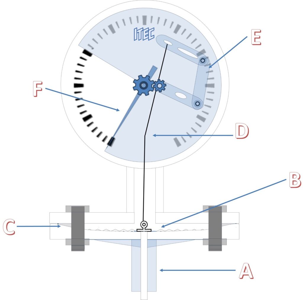
The fluid of interest enters the instrument through the process connector (A), which can be either threaded (such as NPT or BSP) or flanged. It acts on the elastic diaphragm (B), which is typically made of elastic materials in the form of a thin, circular, and flexible disc. This diaphragm can be constructed from stainless steel to withstand corrosion and high temperatures, or from other special alloys, rubber, or plastic, depending on the process conditions and the nature of the fluid. For applications involving particularly aggressive or viscous fluids, diaphragms can be made from materials such as tantalum, titanium, gold, Hastelloy, or coated with PTFE and other highly resistant polymers. Additionally, to protect the wetted parts, even the lower flange of the pressure gauge can be coated with special materials.
The fluid pressure causes the deformation of the elastic diaphragm of the pressure gauge in proportion to the applied pressure, with a measurable deformation that can be converted into a pressure value, typically being linear with respect to the pressure. To ensure linear deflection, the discs of the diaphragms in industrial instruments are usually corrugated, ensuring optimal elastic behavior.
The diaphragm is fixed in a housing (C), which holds it in position while it deforms under the pressure effect. This housing consists of a lower part connected to the pressure inlet and an upper part that supports the diaphragm.
The lower side of the diaphragm is subjected to process pressure, while the upper side is at atmospheric pressure. The elastic deformation of the diaphragm is transmitted through a connecting rod mechanism (D) fixed at the centre of the diaphragm, which in turn activates the rotation of the amplifying movement (E). This movement allows the indication of the pressure value on the dial through the displacement of the pointer. Since the deflection of the diaphragm is extremely small (+/- 1 mm), a high-ratio multiplier mechanism is necessary to enable indication over the entire scale. However, this configuration is possible due to the ability of the diaphragm deflection to generate significant forces.
Features and Applications
Measurement of low pressures: these gauges can measure down to a minimum of 10 mbar, unlike Bourdon spring gauges which can detect pressures starting from 0.6 bar. The standard pressure ranges for membrane gauges are between 10 mbar and 40 bar.
To measure such small pressures, the diaphragm should be ultra-thin to possess sufficient elasticity, making it no longer reliably stable. For extremely low pressure or depression measurement, a special variant of the diaphragm pressure gauge is used, namely capsule gauges. In this type of instrument, the measurement elements are made with two diaphragms welded together, usually pressurized from the inside, resulting in a double movement stroke: this allows the measurement of lower pressures without reducing the wall thickness. However, capsule gauges have the disadvantage of a limited range of application; since the pressure chamber is not self-draining, these instruments are not suitable for applications with aggressive liquids, gases, or gases with possible condensation and can only be used with clean gaseous fluids.
Protection against overpressure: the structure of diaphragm gauges provides good protection against overpressure, as the diaphragm is pressed against the upper chamber when the pressure is excessive. These gauges can withstand pressures up to about 10 times the full-scale value compared to the 1.3 value of a tubular Bourdon gauge.
Protection against vibrations: the annular locking of the diaphragm makes these gauges insensitive to vibrations.
Use with different fluid types: some process fluids can damage the internal mechanism of the gauge, while others can block the pressure port. The process industry can overcome these issues by using a diaphragm pressure gauge; as mentioned earlier, diaphragms can be made from a variety of special materials that make them resistant to specific fluids and/or process conditions while meeting the elasticity and sealing requirements required for measurement. Diaphragm gauges with special materials are essential, for example, in the chemical, petrochemical, oil and gas industries, where fluids are often corrosive, and in water treatment processes, where viscous, crystallizing, or contaminated liquids are present. Flush-mounted diaphragm gauges, where the pressure element is welded directly to the process connection, find extensive use in the food and beverage and pharmaceutical industries, which, working with fluids that require strict hygienic standards, require in-line instrumentation that does not have dead spaces or excessive roughness that could provide an ideal substrate for biofilm formation and microorganism proliferation.
In summary, diaphragm pressure gauges are robust and highly versatile devices that find application in a wide range of industrial sectors, offering precision, reliability, and resistance to the most extreme process conditions.
